MACHINERY

Because of Hefco’s continuing approach to embrace technology to aid in streamlining our production flow,
we are continually adding machinery to accomplish this goal. This means faster production for tighter deadlines and increased accuracy.

MACHINE SPECS

Number of Spindles – 3
Maximum Profile Width – 44″
Maximum Profile Height – 18″
Minimum Profile Width – 3″
Minimum Profile Height – 3/4″
Maximum Weight Section Size – 300 lbs / foot
Maximum Section Weight – 18,000 lbs
Maximum Hole Size – 1-9/16″


55′ INFEED CONVEYORS
60′ OUTFED CONVEYORS

peddinghouse_3

Standard Material Thickness – 3″
Minimum Material Thickness – 1/4″
Maximum Material Width – 126″, 89″, 70″
MinimumMaterial Width – 6″
Max Hole Diameter – 3″
Spindle Power – 48HP

Screen Shot 2015-09-22 at 3.38.49 PM

CUTTING CAPACITY AT 90°

44” wide x 20” High Opening
Plate – 40″x6″x20″
Structural Tube & Pipe – Up to 44” wide
Channel – Up to 44” wide
Solid Material – Up to 44” wide
Angle Iron – Up to 44” wide

CUTTING CAPACITY AT 45° RIGHT – 30.7 wide x 20” high 0pening
CUTTING CAPACITY AT 45° LEFT – 27.9 wide x 20” high opening
CUTTING CAPACITY AT 60° RIGHT – 21.6 wide x 20” high opening
CUTTING CAPACITY AT 60° LEFT – 15.7 wide x 15.7 high opening

Screen Shot 2015-09-22 at 3.39.26 PM

Maximum processing length – 60’
Minimum processing length – 6” Angle
Maximum angle size – 8” X 8” X 1”
Minimum angle size – 1-1/2” X 1-1/2” X 3/16”
Minimum material thickness – 20 gauge

Flat Bar

Maximum bar size – 1” X 12” (maximum 20’ length)
Minimum bar size – 3/16” X 2-1/4” (maximum 20’ length)

Channels

Maximum channel size – 12”
Minimum channel size – 6”
Punch capacity – 143 tons
Maximum hole size – 1-9/16”
Shearing capacity – Up to 425 ton with single cut (up to 300 ton with double cut)
Punching two hole sizes per leg

60’ INFEED CONVEYORS
25’ OUTFEED CONVEYORS

Screen Shot 2015-09-22 at 3.39.37 PM

Capacity at 90° – Rectangular 20″ x 30″
Round 20″
Mitering – 60° left
Operation – Automatic

DOALL C916-A SAW

Capacity
At 90° – 9 in. high x 16 in. wide (228 x 406 mm), 10-3/4 in. rounds (273 mm)
At 45° – 9 in. high x 10-3/4 in. wide (228 x 273 mm wide), 10-3/4 in. rounds (273 mm)
Smallest Diameter – 3/8”

15’ INFEED CONVEYORS
20’ OUTFEED CONVEYORS

Screen Shot 2015-09-22 at 3.39.56 PM

Capacity

Rectangular at 90° – 22″ High X 40″ Wide (25″ Round, 24″ Square)
Rectangular at 45° – 22″ High X 24″ Wide

60’ INFEED CONVEYORS
65’ OUT FEED CONVEYORS

OceanAvenger

The beam line processes:

– Beams
– Angle
– Channel
– Base Plates
– Square and Rectangular Tube
– Round Tube and Pipe

Maximum Beam Size

– Standard machine accepts 40″ beams x 60 ft (any weight, including Jumbos) 60ft x 40″ (18.3m x 1000mm) up to 730 lbs/ft (1088kg/m)
– MAX DRILL DIAMETER 2”
– MIN DRILL DIAMETER .”
– MAXIMUM MATERIAL THICKNESS – UP TO 10”

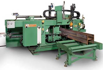
Direct Download from CAD Detailing Programs
The Ocean Avenger Beam Drill Line can be programmed manually at the machine cabinet or can be operated by downloading already detailed parts from your steel detailers CAD detailing program.

The optional Peddinghaus Peddimat software has been the industry standard in the USA for over 20 years and the major steel detailing software companies have all integrated their detailing software with Peddimat.

Screen Shot 2015-12-15 at 3.54.37 PM

– Heavy duty, dual cylinder, completely integrated
– Capacity 6”x 6 x” 11/16”
– 10 HP
– 12” Throat
– 5 work stations
– Simultaneous Dual Operation

top_bender

– Mild steel tube capacity 2-1/2″
– Pipe capacity 2″ Sch. 40
– Square tube capacity 2″
– Maximum CLR 15″
– Bend to CLR as small as 2D
– Touch screen programming of bend angle with system diagnostics in multiple languages
– Quick-change tooling system with multiple radii available
– Digital display of bend angle
– Material springback compensation
– Foot pedal for hands-free operation
– Counterbending die positioning monitored electronically for accuracy and repeatability

ENDUROFAB ATTACK 40 BAND SAW

Cutting Capacity
90° 25” x 40” 25” Round
45° Left / Right 25” x 25”
60° Left 15” x 16”

– Dual Column, Dual Miter, Semi-Automatic Band Saw
– Oversized and Extended Vise Clamp Plates
– Split Front Vise – stabilizes material on both sides of the blade throughout the cut
– Hydraulic Controlled Guide Arm – attached to moveable split vise to ensure accurate guide arm positioning for every cut
– Hydraulic Blade Tension – band tension accurately set on all cuts to increase blade life. When saw is not in operation, tension is released which removes stress on the blade and increases blade life
– Saw head tilted 6º (cant) for structural cutting versatility

bender

– 100mm roll shaft diameter
– Maximum pipe capacity 4″ Sch. 40
– Maximum angle capacity 4″ x 4″ x 1/2″
– Bending speeds 20% faster than competitive machines
– Forged roll shafts precision ground and fitted for maximum performance and minimal deflection
– Heavy duty structure and rigid components for high section modulus ratings
– Reinforced engineered mainframe design proven to outperform competitive models
– Three axis hydraulic twist system for angle iron “Leg-in” applications

HEFCO Enterprises Inc. HEFCO Enterprises Inc.
MENU